Customer's Challenge
The rudder system is one of the crucial components for a vessel. A semi-spade rudder is supported by a horn which consists of a rudder blade with a pintle and the vertical shaft (the rudder stock) which connects blade to the steering gear.
The rudderstock is made of forged steel and a cone coupling is used to fasten the rudder blade to the rudderstock. During repair of the rudder system, machining on both components will be required to maintain the integrity of the contact surfaces. The tapered surfaces between the rudder stock and trunk need to undergo fitting test to achieve a minimum contact of 70%.
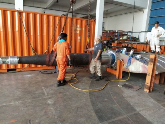
To maneuver the rudder stock (which weighs around 7.5 ton with a length of 6m) and insert into the rudder blade to conduct Prussian blue test is no easy feat.
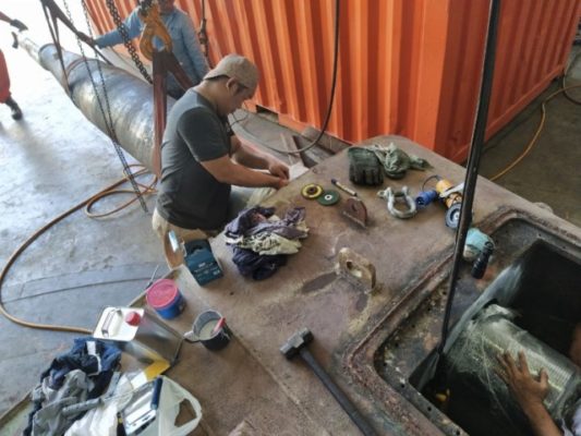
Experience riggers need to handle and maintain the levelness of the rudder stock to prevent any damage to the cone coupling when carrying out the fitting process as shown in Photo 2.
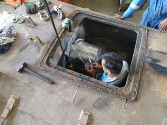
When the rudder stock is inserted into rudder truck, feeler gauge is used to check the clearance of the fitting, as shown in Photo 3.
The rudder stock is then removed in reverse manner to check for at least 70% contact surface. Such process will repeat several times by using manual grinding to achieve the required specification. Each test cycle may takes up to 2 to 3 hours.
Propose solution
By leverage the “Real-time Build & Virtual Assembly” function of Spatial Analyzer software, components can be digitally assembled with relationships and constraint to help visualize how parts will fit in final assembly. By leverage this capability for trial fitting mention above, it will helps minimize the number of blue fit checks needed hence result in man-hours saving and shorter turnaround time.
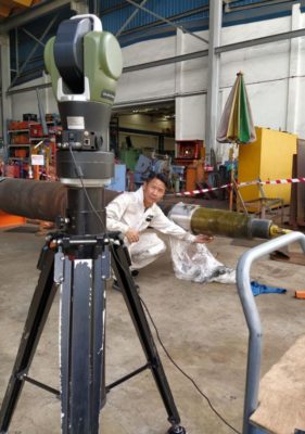
To collect the necessary data, API OmniTrac2 laser tracker was being deployed to conduct measurements on the taper profile on both rudder stock and trunk as shown in Photo 5.
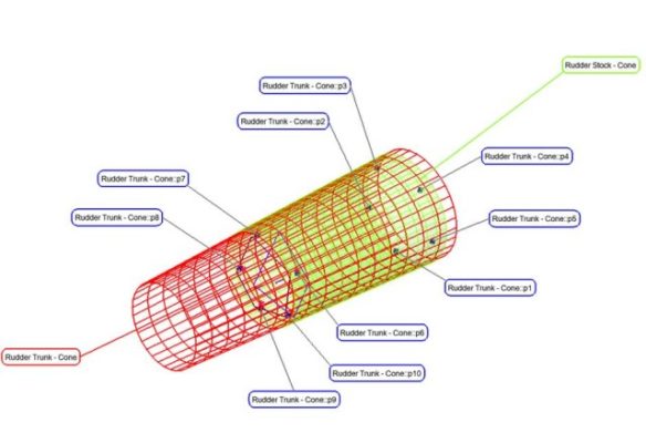
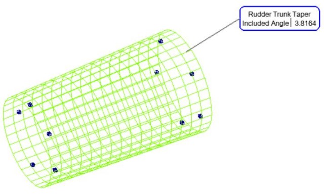
The captured data is then analyzed using the Spatial Analyzer software to verify the taper ratio of the machined parts as shown in Photo 6 and 7.
When the machined parts passed the inspection, the Virtual Assembly function can be activated to simulate the fitting of the cone coupling. Click below to see the simulation video.
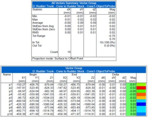
The simulated fitting results in virtual assembly is as shown in Photo 8 and 9.
Through matching the measured points on rudder stock and trunk, the maximum gap deviation between them is around 0.02mm. The accuracy can be further improved by increase the number of measuring points to decide on the corrective actions before commencing the physical fitting process.
Benefits
The laser tracker is able to perform GD&T verifications on mechanical parts swiftly, which has always been a challenge for conventional measuring instruments. By leveraging the capability of Spatial Analyzer software, the digital measured data can be further analyzed to derive other useful information on the machined parts via simulation without the need of physical fittings. This result in reduction of laborious man-hours in trial fittings these large mechanical parts and minimize the risk in damaging the machined parts.


