Enquire Now

why check the pockets in-line?

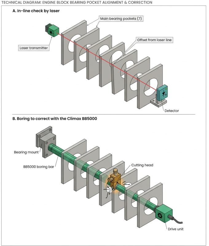
The main bearing pockets in the engine block must lie on one straight centre line. If they do not, the crankshaft bends and loads the bearings unevenly, even when each pocket measures correctly on its own.

When we recommend a check

  • After bearing failure or a spun shell
  • After overheating, grounding or heavy overload
  • After repair work or a new crankshaft
  • Abnormal vibration or repeated bearing wear
  • Crankshaft deflection readings out of limits

What the check tells you

  • How far each pocket is off the common centre line
  • Whether the block is straight or bowed
  • Whether boring is needed, or not

What boring corrects

  • Pocket size and roundness
  • All pockets on one common centre line
  • Correct fit of bearing shells
EQUIPMENT WE USE

Laser alignment system

  • Prüftechnik or Easy-Laser
  • Laser reference line through all main bearing pockets
  • Detector reads each pocket’s centre offset
  • Used before and after boring

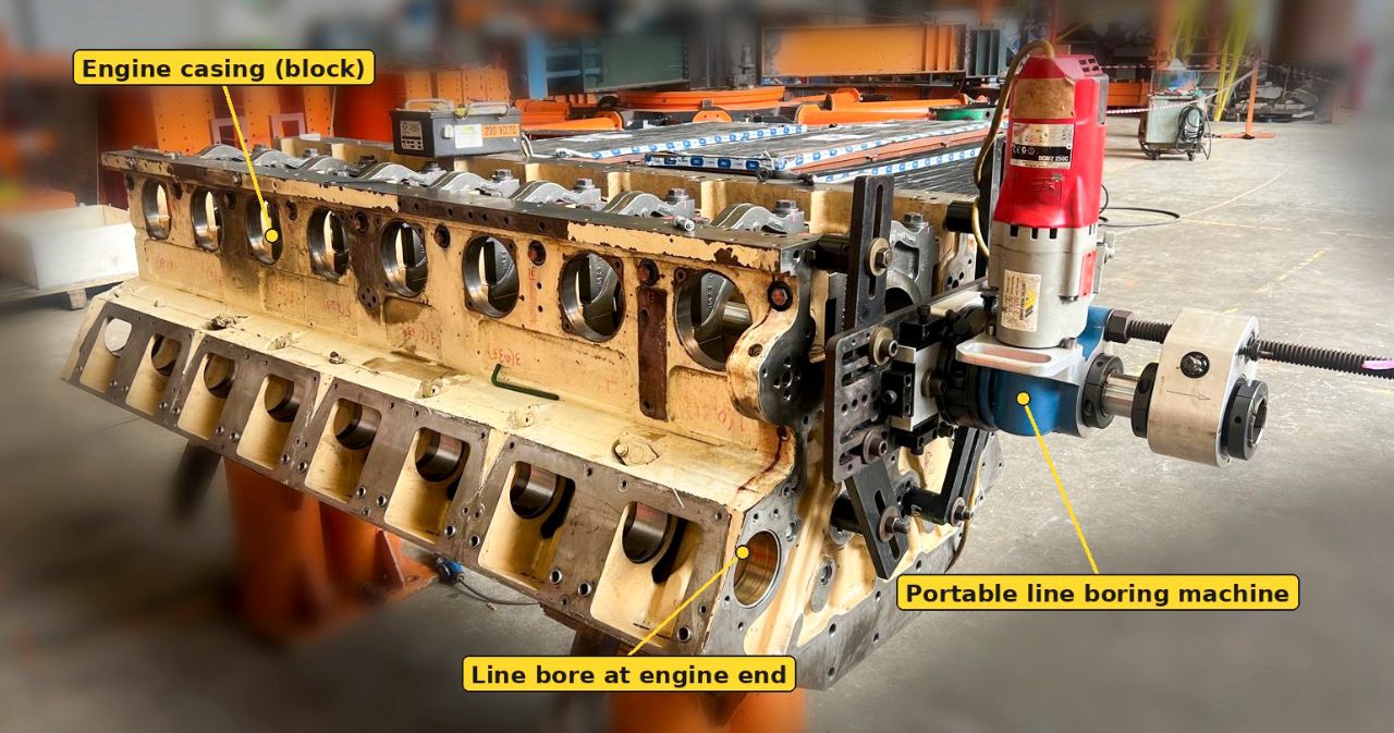
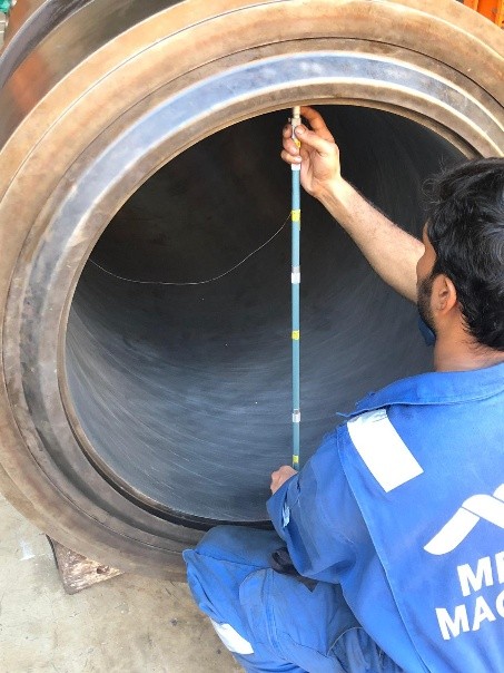
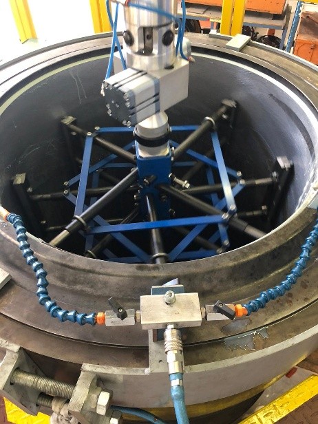
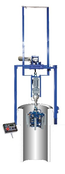
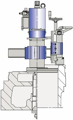
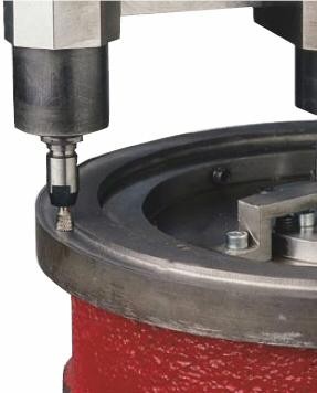
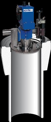
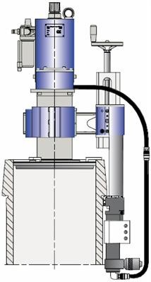
Climax BB5000 portable boring machine

  • Bore range: 38 to 610 mm
  • Bar lengths up to 7.3 m, for long in-line engines
  • High torque drive, up to 881 N·m at the bar
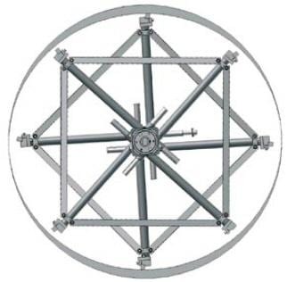
  • Spherical bearing mounts for quick setup

Measuring tools

  • Bore gauges and micrometers
  • Diameter and roundness in several planes
  • All instruments calibrated yearly

BB5000 specifications are as published by the manufacturer. Please send us your engine model so that we can confirm the bar and tooling.

Who carries out the work

Experienced technicians

  • Laser alignment, boring and measurement by our experienced technicians

Trained riggers

  • Handling by trained riggers
  • Supervised by our lifting supervisor, who has completed the Singapore WSH Lifting Supervisor Course

Certified gears, calibrated tools

  • Lifting gears certified yearly
  • Measuring instruments calibrated yearly

bizSAFE Level 4

  • Certified for workplace safety and health management
  • Valid until 12 August 2029

WHERE WE CAN CARRY IT OUT

In-situ

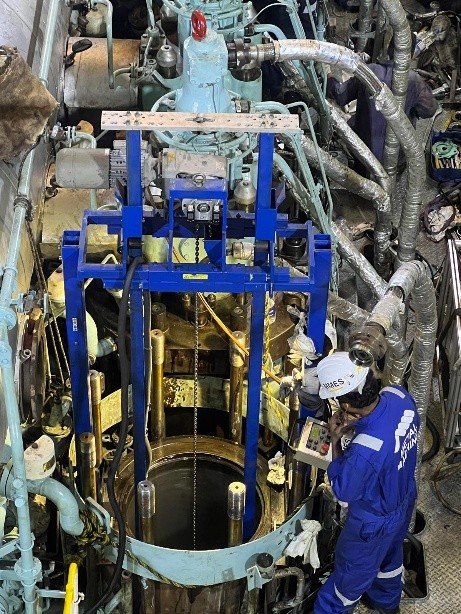
  • In the engine room, with the engine block in place
  • Portable setup: no need to remove the block
  • Onboard, alongside, at anchorage or at a shipyard, by arrangement

In our workshop

  • 16 Tuas Avenue 10, Singapore
  • For blocks and caps removed from the engine
  • 10-ton overhead crane for handling

How we carry out the process

Onboard process

1 Pre-arrival planning
– 
Confirm engine model, bore, units and maker’s limits
– 
Agree work window, access and permits
– 
Prepare equipment and consumables

2 Engine readiness
– 
Crew prepares the unit: piston withdrawn, bore accessible
– 
Engine isolated per vessel procedures
– 
We protect scavenge spaces from debris

3 In-situ measurement
– 
Wear, ovality and taper recorded before work
– 
Compared with the maker’s limits

4 Visual Inspection
– 
Scoring, scuffing, cracks, wear edge at TDC
– 
Dye penetrant on accessible areas on request, by certified technicians
– 
Findings reported to the chief engineer

5 Deglaze and/or hone
– 
Portable machine set up in the liner
– 
Stone pressure, stroke, speed and cross-hatch angle set
– 
Bore checked as work proceeds

6 Top surface grinding
– 
Top sealing surface checked for flatness and damage
– 
Ground where required onboard, using our surface grinding machine

7 Final check
– 
Final bore and roughness measured
– 
Compared with the maker’s specification
– 
Unit released for reassembly

8 Protect and report
– 
Protective film applied to the bore
– 
Before-and-after report to the chief engineer

A. In-line check by laser

1Prepare the engine
  • Crankshaft and bearing shells removed
  • Pockets and caps cleaned

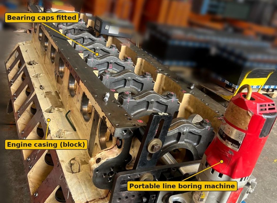
2Fit caps
  • Caps fitted and tightened to the maker’s values

3Set the laser reference
  • Laser set between the end pockets
  • Detector placed in each pocket in turn

4Read and record
  • Centre offset of every pocket, up and sideways
  • Compared with the maker’s limits

5Report and decide
  • Findings sent to you with the readings
  • Within limits: no boring needed
  • Out of limits: boring recommended, with your approval

B. Boring to correct

1Choose the centre line
  • Agree the line to bore to, from the laser readings

2Set up the BB5000
  • Bar mounted through the end pockets
  • Bar aligned to the agreed line
  • Run-out checked before cutting

3Bore
  • Roughing pass, then finishing pass
  • All pockets cut on the same centre line
  • Size checked between passes

4Re-check by laser
  • In-line condition of all pockets re-checked
  • Diameter, roundness and finish verified

5Protect and report
  • Pockets cleaned and protected
  • Before-and-after readings in the report
  • Bearing shell size recommended

B. Boring to correct

1Choose the centre line
  • Agree the line to bore to, from the laser readings

2Set up the BB5000
  • Bar mounted through the end pockets
  • Bar aligned to the agreed line
  • Run-out checked before cutting

3Bore
  • Roughing pass, then finishing pass
  • All pockets cut on the same centre line
  • Size checked between passes

4Re-check by laser
  • In-line condition of all pockets re-checked
  • Diameter, roundness and finish verified

5Protect and report
  • Pockets cleaned and protected
  • Before-and-after readings in the report
  • Bearing shell size recommended

PHOTO GALLERY

Come Talk To Us!

Let us know how we can help you. Send us the engine model, liner marking number, bore size and a few photos, with your preference for workshop or onboard service, and for deglazing and/or honing.